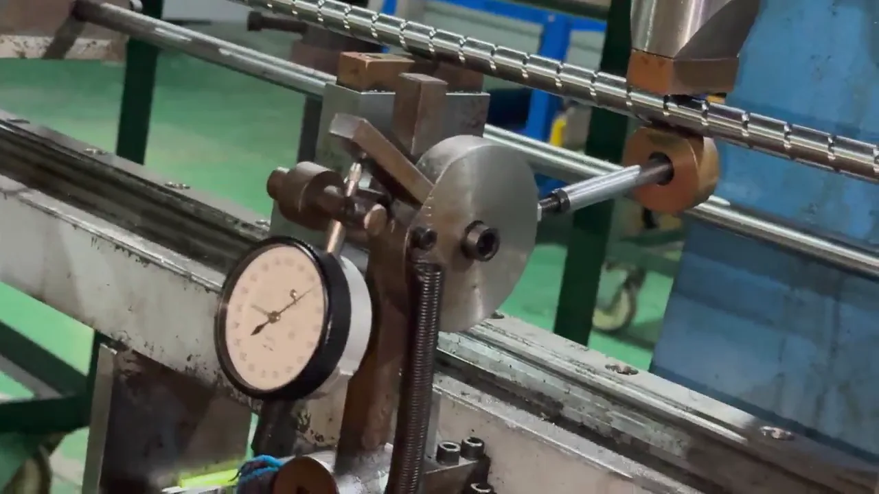
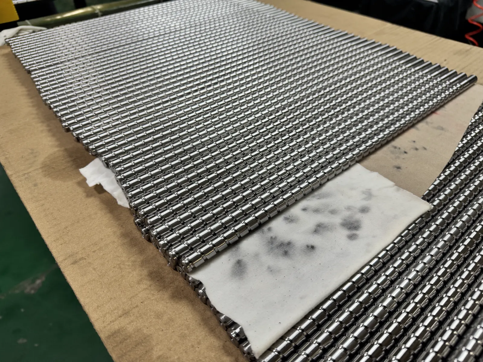
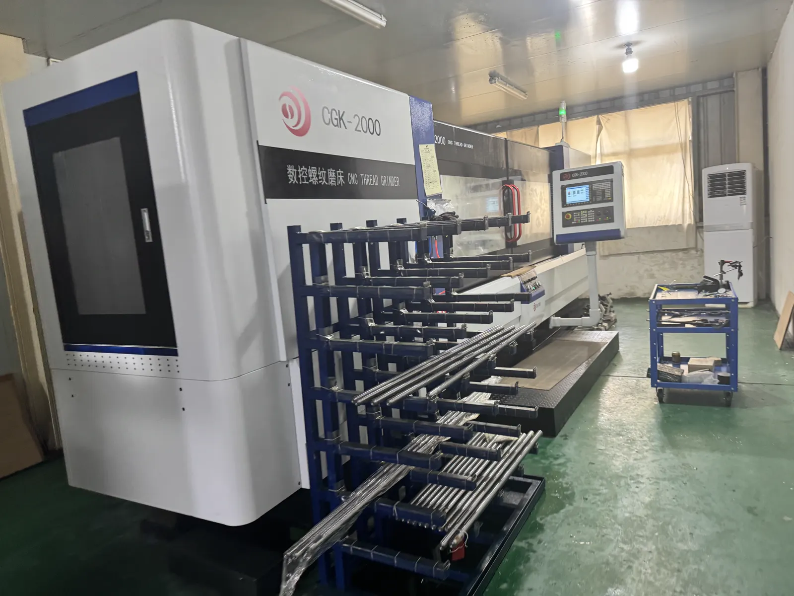
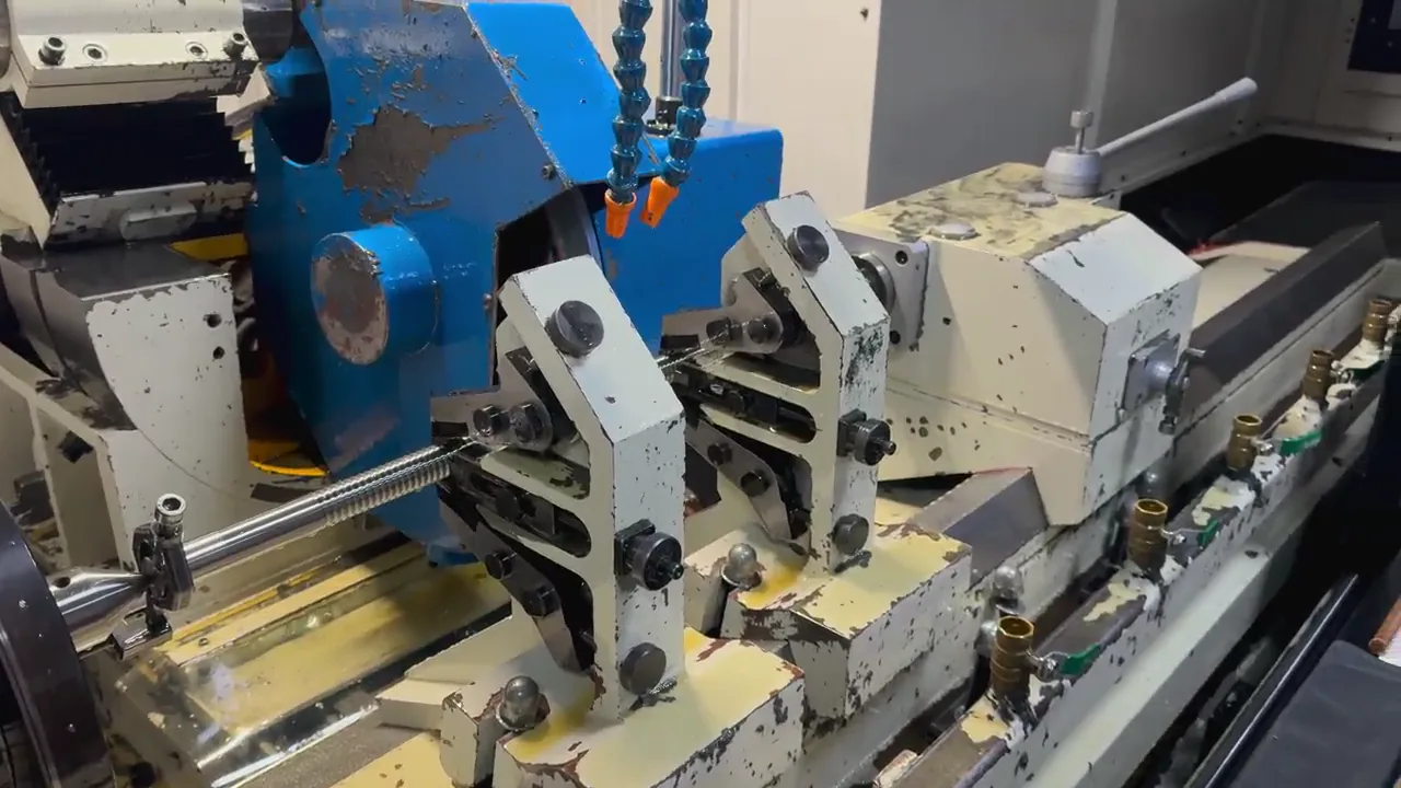
BK/BF Ball Screw End Machining: Support Unit Drawing Guide
Confirm the BK/BF support model before machining the shaft ends, then verify the drawing, bearing seats, threads, coupling end, and assembly length.
Send end machining drawingProducts
Ball screws and matching nuts in SFK, SFU, SFWU, SFS, SFA, SFY, SFG, and straight S/U series. Specify the model, length, and quantity for a quote.
The regular supply scope covers bar stock, standard parts, common models, matching nuts, and assembled sets. Bars ship as full lengths so distributors can build base stock and cut to order later. Standard parts are confirmed by common length and matching nut. Assembled sets put the screw, the nut, and the support units on one list for a single quotation. Model series available to confirm include SFK, SFU, SFWU, SFS, SFA, SFY, SFG, and straight S/U types.
Beyond standard items there are three upgrade routes. Cut-to-length means we cut to the length you give. End machining covers the bearing journal, lock thread, and coupling end, machined to your support unit and end drawing. Custom screws per drawing confirm diameter, lead, length, and shaft-end structure item by item, which suits replacement parts and machine retrofits.
Quotations are confirmed by model, length, quantity, and packing. Naming the target machine, the mounting arrangement, and the support unit in the same message cuts the number of follow-up rounds.
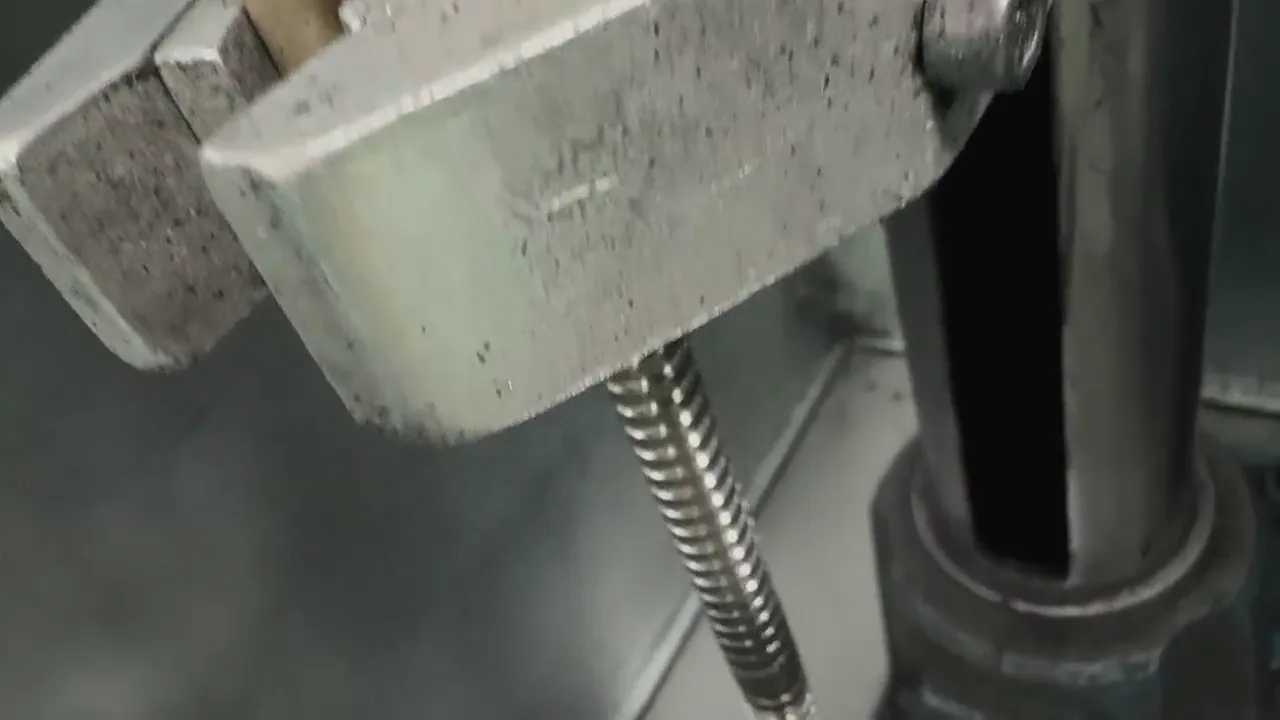
Lead sets the trade-off between speed and thrust. A 5 mm lead favors thrust and positioning control. A 10 mm lead favors travel speed, and under the same drive conditions a 10 mm lead usually delivers lower thrust than a 5 mm lead. Decide which one you cannot give up first, then pick the lead.
Diameter sets rigidity, load capacity, and installation space. 16 mm, 20 mm, 25 mm, and 32 mm are the common steps. A larger diameter gives more rigidity and load capacity and takes more room. On longer axes the speed limit comes from critical speed and the support arrangement, so the support span deserves checking before simply moving up a diameter.
The support arrangement drives the end machining. BK/BF is the common pairing, and FK/FF or EK/EF units can also be confirmed. Once the support model is fixed, the shaft-end journal, lock thread, and coupling end follow from it, so send the support model together with the end drawing. State preload and backlash by application: confirm the preload method when backlash has to be controlled, and note that over-preloading adds friction and heat. Describe the working conditions in the RFQ and decide from there.
| Model | Diameter × lead | Common lengths | Typical use |
|---|---|---|---|
| 1605 | 16 mm × 5 mm | 300 / 500 / 800 / 1000 mm | Small CNC, automation slides, replacement, distributor stock |
| 1610 | 16 mm × 10 mm | 500 / 800 / 1000 / 1200 mm | Small CNC, automation axes, light-duty equipment needing more speed |
| 2005 | 20 mm × 5 mm | 500 / 800 / 1000 / 1500 mm | Medium-small CNC, automation, replacement needing more rigidity |
| 2010 | 20 mm × 10 mm | 500 / 800 / 1000 / 1500 mm | Medium-small CNC, faster motion axes, machine upgrades |
| 2505 | 25 mm × 5 mm | 800 / 1000 / 1500 / 2000 mm | CNC and automation where thrust and positioning come first |
| 2510 | 25 mm × 10 mm | 800 / 1000 / 1500 / 2000 mm | Longer-stroke axes, speed-first CNC and automation |
| 3205 | 32 mm × 5 mm | 1000 / 1500 / 2000 / 2500 mm | Long travel, higher load, stable positioning |
| 3210 | 32 mm × 10 mm | 1000 / 1500 / 2000 / 2500 mm | Long travel with a need for faster movement |
A model number is only a starting point. The same model quoted at different lengths, nuts, and support configurations is a different quotation, so a complete first message usually saves a round of questions.
For replacement work, add the measured overall length, threaded length, shaft-end structure, and nut form of the old part, plus photos. If the dimensions are unclear, send the photos first so they can be checked.
Work through the list below so the first message carries everything needed to quote. Mark anything still open as to be confirmed.
Technical Guides
Read selection, RFQ, machining, and packing articles for this product family before sending an RFQ.
Confirm the BK/BF support model before machining the shaft ends, then verify the drawing, bearing seats, threads, coupling end, and assembly length.
Send end machining drawing
C7 and C5 differ in accumulated lead error, process, and lead time, not in being better or worse. Judge by the axis: most machines run C7, key axes need C5.
Send accuracy requirements
Before requesting a custom ball screw quote, list the drawing, dimensions, accuracy, quantity, and packing requirements.
Open custom RFQ form
State the model, length, nut, packing, and batch plan in a distributor RFQ.
Send distributor purchase list
Choose rolled or ground by the machine accuracy requirement, then compare cost, lead time, preload, and the RFQ details that affect the assembly.
Send accuracy and application requirements
For a BF support-unit RFQ, state the model, shaft journal, lock thread, coupling end, and installation space.
Send support unit RFQProducts
A ball screw is rarely assembled on its own. The same axis usually carries guides, carriages, modules, and support bearings. End machining has to line up with the support unit, and the coupling has to match the motor shaft, so confirming these parts in the same message avoids rework at assembly.
MGN/MGW miniature guides, HGR profile rails, and SBR supported round rails with matching carriages for machine builds, repairs, and distributor orders.
Ball screw-driven linear modules, including compact G7×40 models, with matching motor mounts. Specify travel, load, and speed so the application and quotation can be checked.
Rod-end bearings with male or female threads and spherical plain (joint) bearings for linkage joints, cylinders, conveyors, and automation machines. Radial, angular-contact, and thrust series, with self-lubricating liner options; custom shank lengths and threads available. Send your application and thread size for a quotation.
FAQ
These are the three questions that come up most during selection. The answers depend on your working conditions, not on one fixed model.
A 5 mm lead favors thrust and positioning control. A 10 mm lead favors travel speed, and under the same drive conditions a 10 mm lead usually delivers lower thrust than a 5 mm lead. Decide whether target speed or required thrust comes first. This is the same choice as 1605 against 1610, 2005 against 2010, 2505 against 2510, and 3205 against 3210, and each model page links its comparison article.
A larger diameter gives more rigidity and load capacity and also takes more installation space; 16 mm, 20 mm, 25 mm, and 32 mm are the common steps. On longer axes the speed limit is set by critical speed and the support arrangement, so the support span has to be checked together with the diameter rather than on its own.
Model or drawing, diameter and lead, bar or cut length, threaded length, nut model, support unit model, quantity, packing requirements, and destination country, plus travel, speed, load, and mounting of the target machine. For replacement work add photos and measured dimensions of the old part. Attach the drawing when end machining is required.
+8615268772262
Leave your question or requirement and we will continue in WhatsApp.
Continue in WhatsApp