Guide categories

Ball Screw End Machining Guides

Check support models, end drawings, installation dimensions, and machining risks before quoting.

End machining starts from a drawing because the shaft end is a fitting surface

The screw body is ordered by model. The shaft ends are made to fit the machine. Journals, shoulders, lock threads, and coupling ends touch the support unit, locknut, and coupling directly, so a small difference can block assembly or leave runout once the part is installed. With only a model number and an overall length, the shop has to infer the rest, and a wrong inference sends the whole shaft back for rework.

A drawing states those fits once, in one place. It shows which side is fixed and which side is supported, where the journal length is measured from, how much undercut the thread needs, and whether the coupling end is keyed, flatted, or clamped. Machining and inspection then work from the same reference. For a repair job with no drawing, measuring each step and photographing it is more useful than asking for a copy of the old part.

The support model sets the shaft-end dimensions

BK/BF, FK/FF, and EK/EF are support unit combinations, not screw models. BK, FK, and EK normally sit on the fixed side; BF, FF, and EF on the supported side. Journal diameter, shoulder position, and lock thread differ between the two sides, so the order is to choose the support model and coupling first, then derive the end dimensions from them.

Even the same designation can differ between brands. Check the drawing against the support unit you actually bought, or its dimension table. A usable end drawing should show the diameter and length of each step, the lock thread, shoulder and circlip groove positions, the coupling-end form, and the datum that links overall length to the two ends. With those on the sheet, the machined part has a chance to fit on the first assembly.
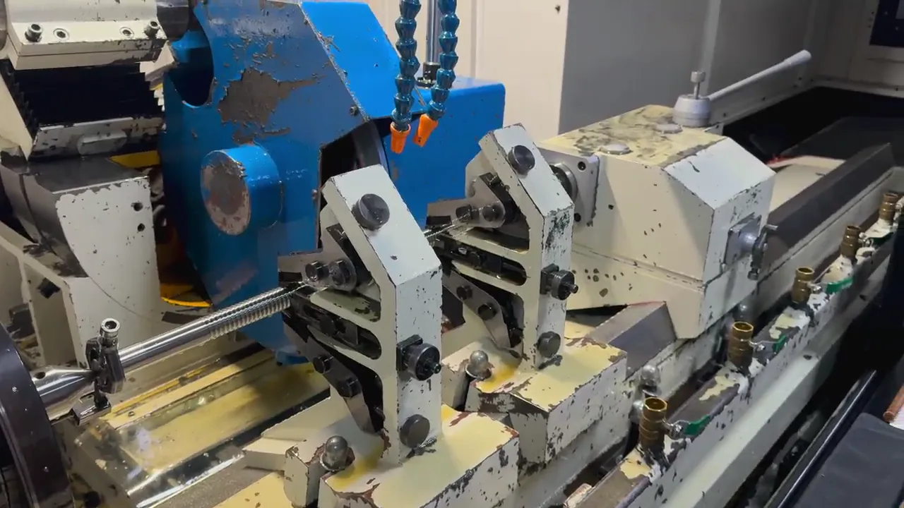
Confirm the BK/BF support model before machining the shaft ends, then verify the drawing, bearing seats, threads, coupling end, and assembly length.
End Machining

BK/BF Ball Screw End Machining: Support Unit Drawing Guide

Confirm the BK/BF support model before machining the shaft ends, then verify the drawing, bearing seats, threads, coupling end, and assembly length.

Send end machining drawing
For a BF support-unit RFQ, state the model, shaft journal, lock thread, coupling end, and installation space.
End Machining

BF Ball Screw Support Unit Suppliers: Buying Guide

For a BF support-unit RFQ, state the model, shaft journal, lock thread, coupling end, and installation space.

Send support unit RFQ
Before end machining, confirm the support-unit model, screw diameter, bearing journal, coupling end, and installation space.
End Machining

BK/BF Ball Screw Support Unit Selection Guide

Before end machining, confirm the support-unit model, screw diameter, bearing journal, coupling end, and installation space.

Send support unit model
Break end machining dimensions into measurable items so buyers can prepare an RFQ without a complete drawing.
End Machining

How to Measure Ball Screw End Machining Dimensions

Break end machining dimensions into measurable items so buyers can prepare an RFQ without a complete drawing.

Send end dimensions

Guide categories

Need help with a different question?

Send the model, length, quantity, application, or old-part photos. We will review the specification against the actual machine and use case.

Send end machining drawing

Shaft-end dimensions the drawing has to show

Before sending an end-machining inquiry, walk the drawing against this list and add whatever is missing.

  • Fixed side and supported side marked separately, with the support model (BK/BF, FK/FF, EK/EF).
  • Journal diameter and length for each step, and the datum each one is measured from.
  • Lock thread size, thread length, and undercut position.
  • Shoulder, circlip groove, and chamfer positions and sizes.
  • Coupling-end diameter, length, and connection form: keyway, flat, or clamp.
  • Relationship between overall length, usable thread length, and mounting position, plus the drawing revision.

FAQ

End machining questions

Three questions that come up most often on end-machining inquiries.

Can you machine from an old part and photos, without a drawing?

Yes, but measure what can be measured: step diameters and lengths, thread size, shoulder positions, and the coupling-end form. Add photos that identify which end is the fixed side. More measured data means less rework.

We already bought the support unit. What else is needed?

Send the support model, and if possible its dimension table or a photo of the actual unit. The same designation can differ between brands, so working from the purchased unit is safer than working from a general table.

If one drawing dimension changes, does it need reconfirming?

Yes. End dimensions depend on each other, and changing a length or thread usually moves the adjacent shoulder. Reconfirm the revision and the machining scope so quotation and production use one file.