Sketch both ends first: record step by step from the end face to the thread
Do not record only one diameter. Separate the fixed side and the support side, then record each step's diameter, length and function in order from the end face towards the threaded section. That is the only form a machinist can work from.
The tools are simple: calipers or a micrometer for diameters, a depth gauge for step lengths, a tape for overall length and thread length. What matters is that each step's diameter, length and function are written together, not as one column of diameters and another column of lengths.
Fixed side: the bearing journal and locking structure matter most
The fixed side usually includes the bearing journal, shoulder, lock thread, undercut and lock nut space. If these dimensions are wrong, the support unit may not fit or the bearing cannot be preloaded correctly. Record each item:
- Bearing journal: journal diameter and bearing seat length. Give the support model as well. A BK12 or BF12 is a support unit model, not the screw diameter. Write both, and attach a photo of the unit or the brand drawing.
- Shoulder: the step that locates the bearing inner ring; give the shoulder diameter and the distance from the shoulder face to the thread.
- Lock thread: normally a fine thread (for example M12×1, M15×1, depending on the support model), and it has to match the lock nut.
- Undercut: at the end of the thread, letting the lock nut seat against the shoulder; give position and width.
Support unit fit is covered in the end machining drawing checklist and the BK/BF end machining guide.
Measure the support side and the coupling end too
The support side is usually simpler: a journal plus a retaining groove or locking arrangement. The motor coupling end needs diameter, length, keyway, flat, or set-screw position. Many installation problems come from unclear coupling end dimensions, not from the screw body.
Overall length, thread length and travel belong together
Overall length alone cannot show whether the nut completes its travel. The thread length has to cover travel plus the nut body, with a small margin at each end; overall length minus the machined ends is the usable travel zone. Writing this relationship down prevents the rework that comes from finding out on assembly that the travel is short.
How to organise the data without a full drawing
- Overall length, thread length and working travel.
- Diameter and length of each step, in order from the end face to the thread.
- Bearing journal, shoulder, lock thread, undercut, keyway and retaining groove.
- Support model, screw diameter, coupling size and photos.
Send the list through the RFQ form; for BK/BF fit checks, review the end machining service first.
FAQ
Why is BK12 not the screw diameter? BK12 and BF12 are support unit models, and the same model number can differ between brands. Give the support model, the brand or a photo of the unit, plus the screw nominal diameter and journal dimensions.
Can you quote without a drawing? Yes. List both ends step by step with diameters, lengths and functions, add the support model and photos, and end machining can be quoted. With photos but no dimensions, we work from the structures that can be identified.
Does end machining change the overall length? No. Material is removed from the same bar to turn the journal, bearing seat and thread, so the overall length is set by the finished dimension. That is the figure to order from.
Next step
Turn this guide into an RFQ
When the specification direction is clear, send the details below together with quantity, lead time, and packing requirements.
Include these details
- Support-unit model, end drawing, or old-part end photos.
- Bearing journal, shoulder, lock thread, keyway, and coupling-end dimensions.
- Overall length, thread length, quantity, inspection, and packing requirements.
Category
Related Technical Guides
Continue with similar buyer questions
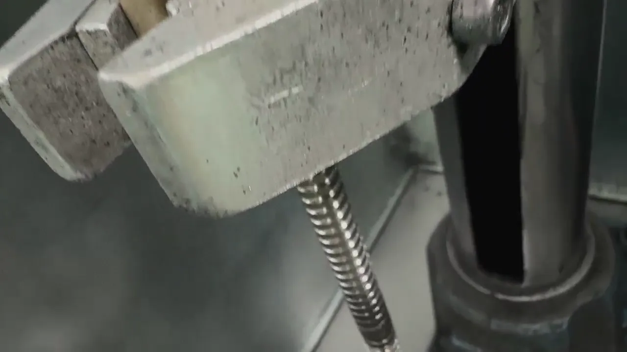
BK/BF Ball Screw End Machining: Support Unit Drawing Guide
Confirm the BK/BF support model before machining the shaft ends, then verify the drawing, bearing seats, threads, coupling end, and assembly length.
Send end machining drawing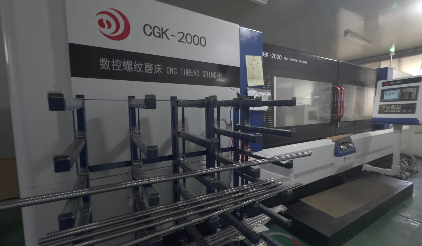
Ball Screw End Machining Drawing Checklist
Before sending an end-machining drawing, check the fixed side, support side, datum, and tolerances.
Send end machining drawing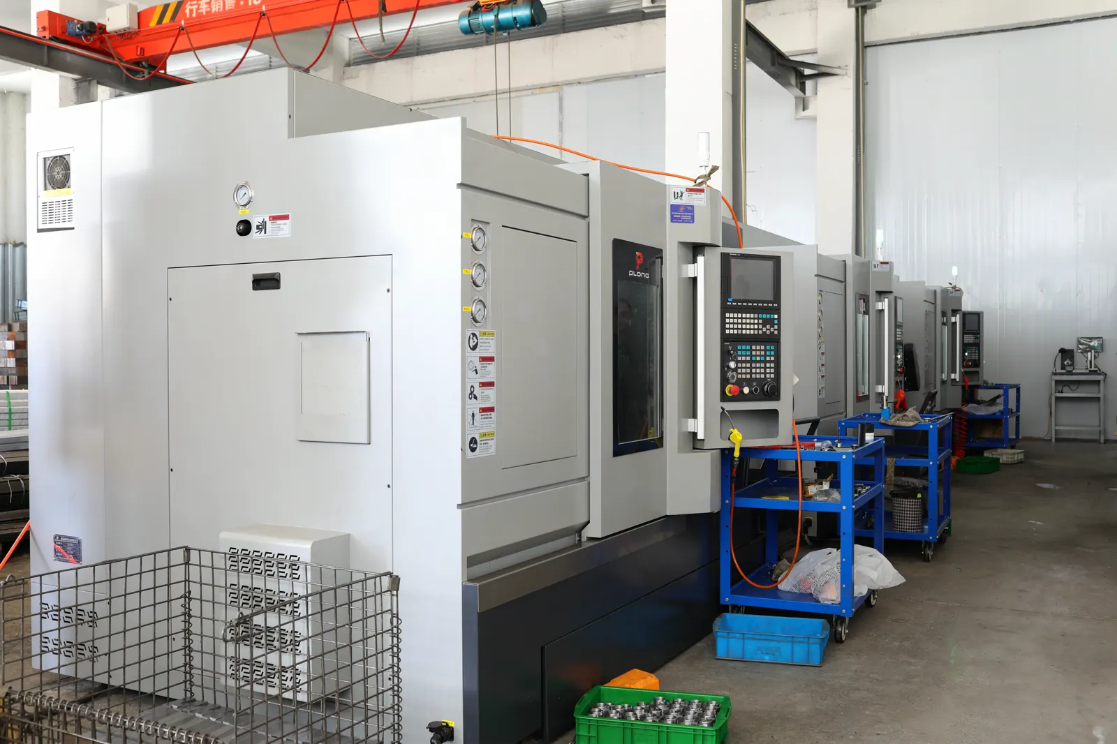
BK/BF Ball Screw Support Unit Selection Guide
Before end machining, confirm the support-unit model, screw diameter, bearing journal, coupling end, and installation space.
Send support unit model